Connecting an Apartment Door Buzzer to a Smarthome Hub
I recently undertook a side project several years in the making, to connect an apartment’s door buzzer to a smarthome system, allowing for more convenience and situational awareness, both at home and on the go.
This post will compile all of the information and resources I gathered over the course of this project, for the benefit of anyone wants to do the same thing!
The Intercom
Many apartment intercom panels look like this one, with a speaker and three buttons:

The traditional apartment intercom user experience goes like this:
- Visitor presses a unit’s button at the front door, triggering a tone at the unit panel
- Resident presses a “talk” button at the unit panel, trying to determine if the visitor is worthy of entry… “who is it?”
- Resident presses a “listen” button on the unit panel to hear the visitor’s response… “It’s me, your visitor!”
- If the visitor is deemed worthy, the resident presses a “door” button at the unit panel, momentarily unlocking the door.
This experience leaves a lot to be desired, and there are myriad benefits to being able to trigger a momentary unlock remotely (even from another room), and to be notified when someone buzzes the apartment.
How does an intercom system like this work, electrically speaking? I’m glad you asked. Here is a schematic of a typical intercom system found in apartment buildings with no doorman/front desk.

The “brain” is the PK-543A, which is installed in a central location in the building. It’s a small plastic box with a circuitboard, lots of wire connections, and dip switches. It connects to the front door panel, an electronic door strike, and to each unit in the building. The unit “intercom stations” can be either 5-wire, 4-wire, or 3-wire, (I think I just figured out why they called it PK “543”) each has slightly different hookups for sending audio and door unlock signals.
According to a 10-second google search, this device runs just over $100, and you could probably score a used one for not too much money if you want to tinker in an isolated environment.
I also learned that the electronics are so elementary that there are lots of off-brand components that work with these intercom systems. You may see more well-known brands like Lee Dan and TekTone, but there are other manufacturers that make compatible button panels (The unit stations and front door panel in the system I modified were made by Apple Core Electronics, but they are all wired to a Lee Dan PK-543A)

The 4-wire unit station is pretty simple as well. There are no complex electronics at all, just switches that connect the incoming wires, and a 45 ohm speaker. The speaker actually doubles as a microphone, making it even simpler:
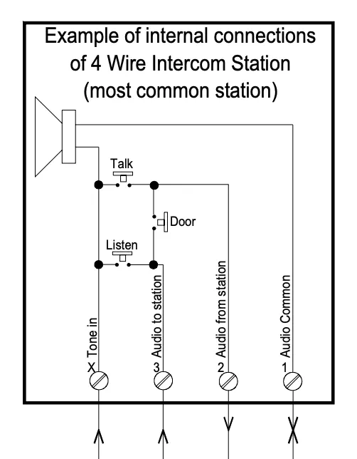
If you unscrew the panel, you’ll see 4 wires, hopefully labeled “X”, “3”, “2”, and “1”. As you would expect, the talk and listen buttons route current through the speaker/mic. The door button simply connects wires 2 and 3, which the central unit can sense and then trigger the unlocking of the door.
Choosing a Bridge Device
The “dumb” system requires a human to listen for the tone and press the button to unlock the door. Making the intercom interface “smart” means setting things up so a computer can do the two functions a human used to do:
- Sense a call to the unit station, which can be used to trigger a notifications or other actions.
- On demand, trigger a 3-second door unlock (simulate a human pushing the button long enough for a visitor to open the door)
To accomplish these, we need a piece of smarthome hardware called a bridge, or IO (Input/Output) interface. A bridge is a generic device that can communicate with the smarthome network and act as an electrical sensor and/or actuator.

The MIMOlite by Fortrezz does exactly this. It uses Z-Wave to communicate via mesh network with a Samsung SmartThings smarthome hub (or any other Z-Wave compatible system).
It’s got a pretty simple physical interface. Two wires give it power (via a 12V AC adapter), two wires connect to its sensing input, and three wires connect to its switching relay (as with most relays, you can have it either close a circuit or open a circuit)
For those who know more about Z-Wave, the MIMOlite has the following command classes we can use for this project (among others, read the technical appendix for more):
SENSOR_BINARY — The signal input can send a Z-Wave command when it enters and leaves a triggered state. The triggered state can either be a dry contact, or a configurable voltage range. Other Z-Wave devices can also “ask” what the current state of the sensor is.
SWITCH_BINARY — Z-Wave devices can send On and Off commands, controlling the relay. Z-wave devices can also “ask” what the current state of the switch is.
So, the MIMOlite will become the “smart” interface for a “dumb” intercom panel. But how do we hook it up?

Triggering the Door
The door trigger is the easier side of this connection problem. We already know that the panel is just connecting wires 2 and 3, so all we need to do is connect these two wires to the MIMOlite’s relay in parallel.

With this configuration, both the button and the MIMOlite can close the circuit independently, so we aren’t changing any of the original functionality of the intercom panel.
But how can we ensure that the door release is only triggered for a moment? The default solution would be to simply treat it as a switch, and have whatever is doing the triggering also do the timing:
Turn switch On > Wait 3 seconds > Turn switch Off
This feels risky, because if there’s any error with the transmission of the Off command, the door could remain unlocked indefinitely. Lucky for us, the MIMOlite has a configuration parameter for momentary relay output!

Parameter 11 is the time to engage the relay after an On command is received, in increments of 100 milliseconds. Setting it to “30” means the relay will engage for 3 seconds, enough time for our visitors to open the door and enter. (See the Custom SmartThings Device Handler section below for how we set the Z-Wave Parameters on the MIMOlite)
This solution is safer and more reliable, as the logic to time the relay closure is happening on the MIMOlite itself, and is not subject to potential transmission issues over the Z-Wave network or the internet.
Detecting a Buzz
Detecting a buzz would turn out to be the trickier problem, and required some custom electronics. When a visitor buzzes the unit from the entry door panel, an audio signal is sent via the “X” wire, through the speaker, returning to ground via the “1” wire.

This took me several days of searching and tinkering. I originally set out searching for ways to sense an audio signal flowing through a speaker. Since audio is alternating current, lots of online forums led to recommendations for adding DC bias to the signal, then smoothing the signal so it could be sensed by an analog to digital converter.
A lot of people used this kind of circuit to make an LED VU meter for an audio signal using an Arduino or similar microcontroller.
I later learned from the PK543A wiring diagram that the tone signal is not AC, it’s pulsed DC.
I found lots of similar circuits online, and even got some recommended circuits from electrical engineers, but a few days in I learned via an obscure reddit thread that TekTone used to sell a simple add-on board that did exactly what we want to do. It was called the RY014B, and it could sense an intercom tone signal and close a relay!
There is surprisingly little information on the internet about the RY014B, but it’s clear from this grainy image (and a redditor’s description in the thread above) that it’s just a diode, a capacitor, and small relay. It’s discontinued. You can find some spec sheets for it, but nothing that actually tells you what the components are.
I probably could have reverse engineered this with trial and error, but was able to track down the details via the reddit user who first made mention of this module. Here is a detailed circuit diagram, for anyone who comes along after me and needs to sense an intercom’s tone.

This circuit is wired in parallel with wires X and 1 in the intercom panel. When the unit’s button is pressed at the front door, the relay closes. Since the MIMOlite’s input can function as a dry contact, we just wire it up to the relay and call it a day. With its default configuration, the MIMOlite will send a Binary Sensor Report when the two terminals of the input are connected. The door buzzer is smart!

SmartThings Custom Device Handler
The MIMOlite is a Z-Wave device, but it’s not hooked up to the internet… it can only communicate with other Z-Wave devices. While there are many ways to communicate with devices over Z-Wave, the most popular are the consumer smarthome platforms. Samsung SmartThings is one of these, and provides hardware and tooling for controlling Z-Wave and other smarthome devices.
Device Handlers are SmartThings’ device configurations, defining what functionality is available for a device, providing for basic User Interface building and configuration. When you add a device to your network, SmartThings requires you to specify a device handler. For example, because most Z-Wave dimmers respond to the same On, Off, and Dimmer percentage commands, there is a generic Device Handler for Dimmers. Some manufacturers will make custom Device Handlers for their specific product, which you can choose from a list when adding the product to your smarthome network.
The MIMOlite, however, is both a sensor and a switch in one device, so a generic Device Handler won’t do. We need a custom device handler that exposes both the sensor and the switch to our SmartThings network.
Fortrezz has published a generic Device Handler for the MIMOlite on github. It contains basic UI tiles that show up in the SmartThings app, allowing you to sense the voltage on the input and turn the switch on and off.

I modified this Device Handler, trimming down things I don’t need, using a door lock icon, leaving only the switch, dry contact, configuration, and refresh functionality. I won’t get too into the weeds on the code, which is in a java-like language called groovy. It should be commented well enough for you to follow along.
Suffice to say that the SmartThings classic app is probably on its way out, and not the best way to interact with a smart door buzzer. I find it useful for testing, but the real value of getting this thing connected to SmartThings is all of the other things SmartThings connects to, such as Alexa or If This Then That (IFTTT), or even a custom iOS app (which I may write if I can find the time).
For example, when someone buzzes the unit, I could grab a still image from the networked camera that’s looking at the entry door, and send a push notification to my phone notifying me that someone is at the door with a photo. To go one step further, the notification could include action buttons allowing me to unlock the door without going to another app. If I do any of this, I’ll be sure to write it up and share a link here.
Thanks to Tom Johnson and James Whong for electronics help, and to reddit user johnny121b for providing info on the RY014B. Thanks to you for reading this, please leave comments and questions if you have them!